
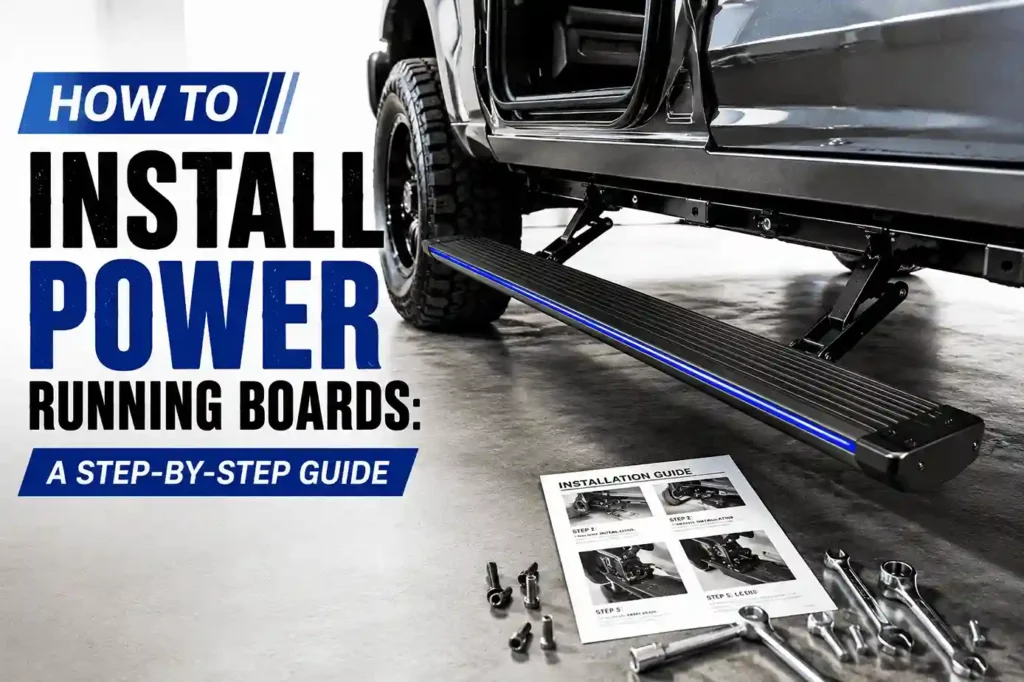
To install power running boards, you need to complete two main tasks: mechanical installation and electrical wiring. The first task secures the running boards, mounting brackets, and motors to the vehicle. The second task connects the wiring harness, control module, power supply, and door signals.
The installation method varies by vehicle. Each model may use different brackets, wiring locations, and signal connections. Check the installation instructions for your vehicle before starting the job.
This guide covers the basic steps to install power running boards. We also use a Ford F-150 installation as a real example. The example shows how the mounting, wiring, and signal connections work on an actual vehicle.
What You Need Before Installing Power Running Boards
Before you install power running boards, check the vehicle and the installation kit. A correct match helps prevent fitment and wiring problems.
Check Vehicle Compatibility
Start by confirming the vehicle information. Check the following details:
- Vehicle make
- Model
- Tahun model
- Cab or body configuration
- Correct running board kit
The running boards must match the vehicle. The mounting brackets should fit the vehicle frame or factory mounting points. The wiring harness should also match the vehicle and control system. A kit for the wrong model may have different brackets, wiring locations, or signal connections.
Check the Installation Components
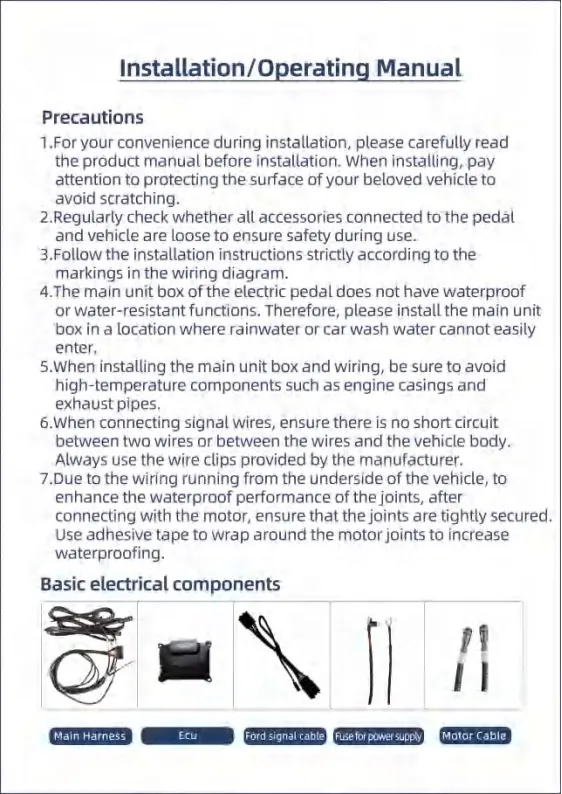
A typical power running board kit includes several mechanical and electrical parts. Check all components before you start the installation.
| Komponen | Function |
|---|---|
| Running boards | Main step for getting into the vehicle |
| Braket pemasangan | Attach the boards to the vehicle |
| Motors | Move the running boards |
| ECU | Controls the running board system |
| Main harness | Connects the electrical components |
| Signal cable | Receives vehicle signals |
| Fuse | Protects the power circuit |
| Motor cables | Connect the motors to the system |
Lay out the parts before installation. This simple check can save time later. If a bracket, cable, or connector is missing, you can find it before the vehicle is on the lift or jack stands.
Prepare the Vehicle
Prepare the vehicle before you start mechanical work or wiring.
- Park the vehicle on a flat and safe surface.
- Protect the vehicle surface from scratches.
- Identify the left and right installation positions.
- Make sure you can access the required wiring areas.
- Remove seats or trim panels only when the vehicle-specific instructions require it.
Keep the installation area clean and organized. Place the brackets, cables, and other parts where you can identify them easily. This makes the next installation steps faster and reduces the chance of connecting the wrong component.
How to Install Power Running Boards Step by Step
Once the vehicle and installation kit are ready, you can start the installation. The process usually follows a clear order: identify the brackets, mount the running boards, install the motors, connect the wiring, and test the system.
The exact steps can vary by vehicle. Follow the vehicle-specific installation instructions for bracket positions and wiring connections. The steps below use a Ford F-150 as a practical reference.
Power Running Board Installation Overview
| Langkah | Installation Task | Main Purpose |
|---|---|---|
| 1 | Identify the Left and Right Brackets | Match each bracket to the correct vehicle position |
| 2 | Locate the Vehicle Mounting Points | Find the correct mounting locations |
| 3 | Install the Mounting Brackets | Secure the brackets to the vehicle |
| 4 | Attach the Running Boards | Mount and align the running boards |
| 5 | Install the Motors | Install and connect the left and right motors |
| 6 | Install the ECU | Mount and protect the control unit |
| 7 | Connect the Vehicle Signal | Connect the vehicle signal to the ECU |
| 8 | Connect Power and Ground | Provide power and a proper ground connection |
| 9 | Install the Fuse | Protect the power circuit |
| 10 | Connect the Left and Right Motor Wires | Connect each motor to the correct wiring |
| 11 | Secure and Waterproof the Wiring | Protect the wiring from heat, water, and damage |
| 12 | Test the Power Running Boards | Check opening, closing, alignment, and system operation |
This overview gives you the complete installation sequence before you start the detailed steps below.
Step 1. Identify the Left and Right Brackets
Before mounting the brackets, check the labels on each bracket. Most kits use position codes to show where each bracket belongs:
- LF = Left Front
- LR = Left Rear
- RF = Right Front
- RR = Right Rear
Match each bracket with its correct position on the vehicle. Do not install the brackets based only on their shape. The front and rear brackets may look similar but can have different mounting holes or angles.
Place the brackets beside the vehicle first and confirm the left and right positions. This simple check can prevent you from removing and reinstalling a bracket later.
Step 2. Locate the Vehicle Mounting Points
Find the mounting points on the vehicle before installing the brackets. Compare the mounting points with the product installation diagram and confirm the correct positions.
Mounting points can vary by vehicle. Different models may use different locations, bracket shapes, and mounting holes. Do not assume that the same mounting method works for every vehicle.
If the vehicle requires any additional work before bracket installation, follow the vehicle-specific installation instructions. Use the correct mounting points shown in the instructions before securing the brackets.
Step 3. Install the Mounting Brackets
Align each mounting bracket with the correct mounting point on the vehicle. Make sure the bracket sits in the position shown in the installation instructions.
Secure the brackets with the supplied hardware. Tighten the fasteners enough to hold the brackets in place, then check that each bracket is stable and has no obvious movement.
Before installing the running boards, check the space around each bracket. Make sure the brackets do not interfere with the vehicle body, frame, suspension parts, wiring, or other nearby components.
- Check these points before moving to the next step:
- Confirm that there is enough space for the running boards and motors to move freely.
- Make sure each bracket is installed in the correct position.
- Check that all mounting hardware is secure.
- Make sure the brackets do not contact nearby vehicle parts.
Step 4. Attach the Running Boards
Align each running board with the correct mounting brackets. Check the left and right sides before securing the boards. Make sure the mounting holes line up with the brackets and use the supplied hardware to attach the boards.
Before fully tightening the hardware, check the position of the running board along the vehicle. Make sure it sits level and has enough clearance for normal movement.
Check these points before moving to the next step:
- Make sure the running board is level and straight.
- Check that the board does not contact the vehicle body or brackets.
- Make sure there is enough clearance for the board to move freely.
- Confirm that all mounting hardware is in the correct position.
Step 5. Install the Motors
Install each motor in the mounting position specified for your vehicle. The motor mounting position can vary between vehicle models, so follow the vehicle-specific installation instructions.
Connect the left and right motors to their corresponding motor cables. Make sure each connector is fully connected and secured before moving on to the wiring installation.
Keep the motors and wiring away from the exhaust system and other high-temperature components. Secure the cables so they do not hang near moving parts or areas that could cause damage.
Check these points before moving to the next step:
- Install each motor in the correct vehicle-specific position.
- Connect the left and right motors to the correct cables.
- Make sure all motor connectors are fully connected.
- Keep the motors and wiring away from exhaust and other high-temperature parts.
- Secure the wiring away from moving or sharp components.
Step 6. Install the ECU
Install the ECU or controller inside the vehicle. Choose a dry and secure location that is protected from rainwater, car-wash water, and other sources of moisture. The ECU is not waterproof, so do not install it in an exposed area.
Keep the ECU away from the engine, exhaust system, and other high-temperature components. Use zip ties or another reliable mounting method to secure the ECU firmly in place.
A loose ECU can move or vibrate while driving. This may cause abnormal noise and can also put stress on the wiring and connectors.
Check these points before moving to the next step:
- Install the ECU inside the vehicle in a dry location.
- Keep the ECU away from rainwater and car-wash water.
- Keep the ECU away from the engine, exhaust, and other high-temperature parts.
- Secure the ECU firmly with zip ties or another reliable mounting method.
- Make sure the ECU and its wiring cannot move or rattle during driving.
Step 7. Connect the Vehicle Signal
The vehicle signal tells the power running boards when to open and close. The basic connection logic is:
Vehicle Signal → Signal Adapter → Main Harness → ECU
The exact signal connection depends on the vehicle. Some vehicles may use an OBD/CAN connection, while others may use a vehicle-specific signal connection. Because the wiring layout can differ between models, always follow the wiring diagram provided for your vehicle.
For power running boards wiring, connect each signal cable to the correct connector and make sure the connections are secure. Do not guess the signal location or connector based on another vehicle model.
If you are learning how to wire power running boards, focus on the correct signal path rather than using the same connection method for every vehicle.
Check these points before moving to the next step:
- Confirm the correct vehicle signal connection.
- Connect the signal adapter to the correct vehicle signal.
- Connect the signal adapter to the main harness.
- Connect the main harness to the ECU.
- Follow the vehicle-specific wiring diagram for all signal connections.
Step 8. Connect Power and Ground
Connect the power supply according to the vehicle-specific wiring diagram. Confirm the positive and negative connections before connecting the system to the vehicle power supply.
The ground connection needs good contact with bare metal. Do not connect the ground wire through plastic, painted surfaces, or other materials that can prevent a proper electrical connection.
Keep the power wiring away from the exhaust system and other high-temperature components. Secure the wiring so it stays in place during driving.
Check these points before moving to the next step:
- Follow the vehicle-specific wiring diagram for the power connection.
- Confirm the positive and negative connections.
- Connect the ground wire to a clean bare-metal surface.
- Do not use plastic as the ground contact point.
- Keep power wiring away from exhaust and other high-temperature components.
- Secure the wiring to prevent movement or damage.
Step 9. Install the Fuse
Power running boards normally require a fuse in the power circuit. Install the fuse according to the vehicle-specific wiring diagram and the instructions included with the running board kit.
Some vehicles may already have a suitable fuse location or fuse slot. If the vehicle has a designated fuse position, follow the product instructions for that connection. If the kit uses a separate fuse slot, install it in the specified location and confirm the correct insertion method.
The fuse location and installation method can vary by vehicle. Do not assume that all vehicles use the same fuse position or fuse slot.
Check these points before moving to the next step:
- Confirm the correct fuse location for your vehicle.
- Follow the product wiring diagram for the fuse connection.
- Check whether the vehicle already has a designated fuse position.
- Confirm the correct fuse slot and insertion direction.
- Make sure the fuse is securely installed before testing the system.
Step 10. Connect the Left and Right Motor Wires
Connect the left motor wire to the left motor and the right motor wire to the right motor. Check the labels on the connectors before making the connections to avoid connecting the motors to the wrong side.
Make sure each connector is fully seated and securely connected. Route the motor wires so they have enough slack and are not pulled tightly by the movement of the running boards or other vehicle components.
Check these points before moving to the next step:
- Connect the left motor wire to the left motor.
- Connect the right motor wire to the right motor.
- Make sure the left and right motor wires are not reversed.
- Confirm that each connector is fully seated.
- Make sure the connectors and wires are not under tension or being pulled.
Step 11. Secure and Waterproof the Wiring
After connecting all electrical components, secure and protect the wiring. Keep the wires away from the exhaust system and other high-temperature components. Use clips, zip ties, or other suitable fasteners to keep loose wiring in place.
Route the wires away from sharp edges and moving parts. Protect the motor wire joints with adhesive tape where required. Keep connectors that are not waterproof inside the vehicle and protect them from water and moisture.
If the wiring passes through the vehicle chassis, seal the wiring holes with the supplied silicone. This helps prevent water from entering the vehicle through the openings. Before testing the system, check that all connectors are fully connected and secure.
| Do | Don’t |
|---|---|
| Secure loose wiring with clips or zip ties. | Leave wires hanging loose. |
| Seal chassis wiring holes with supplied silicone. | Leave wiring openings exposed. |
| Keep the ECU inside the vehicle. | Install the ECU in a wet or exposed area. |
| Keep wiring away from exhaust and other high-heat parts. | Route wires next to the exhaust system. |
| Protect motor wire joints with adhesive tape. | Leave motor connections exposed. |
| Make sure all connectors are fully connected. | Leave connectors loose or partially connected. |
Power Running Boards Wiring Diagram Explained
Basic Wiring Logic
The basic wiring structure of power running boards is simple:
Vehicle Power → Fuse → ECU → Motor
The vehicle power supplies electricity to the system. The fuse protects the power circuit. The ECU controls the running boards and sends commands to the motors.
The vehicle signal follows a separate path:
Vehicle Signal → Signal Adapter → Main Harness → ECU
The vehicle signal tells the ECU when the running boards should open or close. This basic wiring logic helps you understand how the system works. The actual connection method can vary by vehicle and power running board kit, so always follow the vehicle-specific wiring diagram.
Main Wiring Components
| Connection | Purpose |
|---|---|
| Vehicle power | Supplies electrical power to the system |
| Fuse | Protects the power circuit |
| Signal cable | Sends vehicle or door signals |
| Main harness | Connects the main electrical components |
| ECU | Controls power running board operation |
| Motor wires | Connects the ECU to the motors |
Important Wiring Precautions
Correct wiring is important for safe and reliable operation. Always use the wiring diagram supplied with the power running board kit instead of assuming that every vehicle uses the same connection method.
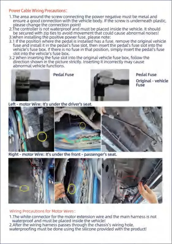
Check these points before testing the system:
- Follow the vehicle-specific wiring diagram.
- Check all positive, negative, and signal connections.
- Avoid short circuits during installation.
- Keep the ECU dry and protected from water.
- Make sure all connectors are fully seated.
- Secure wiring under the vehicle with suitable clips or zip ties.
- Keep wiring away from exhaust systems and other high-temperature parts.
How to Install Power Running Boards on a Ford F-150
The Ford F-150 is a good example of why power running board installation should follow a vehicle-specific guide. The bracket positions, OBD connection, power connection, motor wiring, ground point, and fuse installation all depend on the vehicle layout.
The steps below follow the installation process for the F-150 power running board kit. For the complete installation procedure and vehicle-specific diagrams, see the F-150 power running board installation instructions
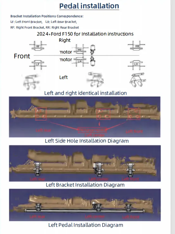
F-150 Bracket Installation
The F-150 kit uses four main bracket positions: LF, LR, RF, and RR. These labels identify the left front, left rear, right front, and right rear mounting positions.
Install the left and right brackets according to the corresponding installation diagrams. Match each bracket with the correct F-150 mounting point before tightening the hardware.
After installing the running boards, check their alignment along the vehicle. Make sure both sides sit at the correct height and have enough clearance for normal operation.
Check these points before moving to the next step:
- Confirm the LF, LR, RF, and RR bracket positions.
- Follow the corresponding left and right installation diagrams.
- Install each bracket at the correct F-150 mounting point.
- Check running board alignment after installation.
- Make sure the boards have enough clearance to move freely.
F-150 OBD Signal Connection
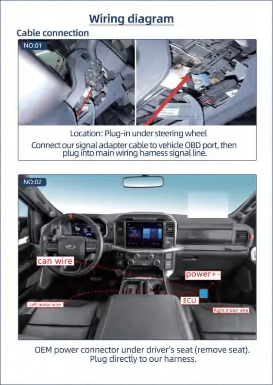
The F-150 kit uses the vehicle OBD port to receive the required vehicle signal. The basic connection path is:
OBD Port → Signal Adapter Cable → Main Harness Signal Line
The OBD port is located in the area below the steering wheel. Connect the signal adapter to the vehicle OBD port, then connect the adapter to the signal line on the main harness.
Make sure both connections are fully seated before moving to the next wiring step.
Check these points:
- Locate the OBD port below the steering wheel.
- Connect the signal adapter to the vehicle OBD port.
- Connect the adapter to the main harness signal line.
- Make sure both connectors are fully connected.
- Route the wiring so it does not interfere with the driver’s area.
F-150 Power Connection
The F-150 OEM power connector is located under the driver’s seat. Remove the driver’s seat when necessary to access the connector and create enough working space.
Connect the power cable according to the provided F-150 wiring diagram. Because the power connection is vehicle-specific, do not use the wiring method from another vehicle as a reference.
After making the connection, secure the wiring so it does not move freely under the seat.
Check these points:
- Locate the OEM power connector under the driver’s seat.
- Remove the seat when necessary to access the connector.
- Follow the provided F-150 wiring diagram.
- Make sure the power connection is fully connected.
- Secure the wiring under the seat.
F-150 Motor Wiring
The left motor wire is routed under the driver’s seat, while the right motor wire is routed under the front passenger’s seat. Connect each motor to its corresponding motor wire.
The white motor extension connector is not waterproof. Keep this connector inside the vehicle where it is protected from water and moisture.
When the motor wiring passes through the vehicle chassis, seal the wiring hole with the supplied silicone. This helps prevent water from entering the vehicle through the wiring opening.
Check these points:
- Route the left motor wire under the driver’s seat.
- Route the right motor wire under the front passenger’s seat.
- Keep the white motor extension connector inside the vehicle.
- Do not expose the non-waterproof connector to water.
- Seal the chassis wiring hole with the supplied silicone.
F-150 Ground Connection
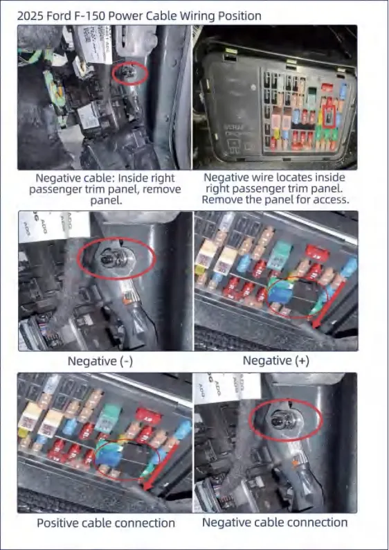
The negative cable connection is located inside the right passenger trim panel. Remove the trim panel to access the connection area.
The grounding screw must make direct contact with metal. A plastic-covered connection point cannot provide the required metal contact for the ground connection.
After connecting the ground cable, make sure the connection is secure and the grounding point has good metal contact.
Check these points:
- Locate the negative cable connection inside the right passenger trim panel.
- Remove the panel to access the connection area.
- Make sure the grounding screw contacts metal.
- Do not use a plastic-covered connection point.
- Make sure the ground connection is secure.
F-150 Fuse Installation
The fuse installation on the F-150 follows the vehicle-specific fuse layout in the installation instructions.
If the corresponding vehicle fuse position already has a fuse, remove the original fuse first. Install the removed fuse into the running board fuse slot. Then insert the running board fuse slot into the corresponding position in the vehicle fuse box.
If there is no fuse in the specified vehicle position, install the running board fuse slot directly according to the installation instructions.
Pay attention to the specified insertion direction. The fuse slot must be installed in the correct direction and position before the power running board system is tested.
Check these points:
- Check the specified fuse position in the F-150 fuse box.
- If a fuse is already installed, remove the original fuse.
- Install the original fuse into the running board fuse slot.
- Insert the running board fuse slot into the vehicle fuse box.
- If no fuse is present, install the running board fuse slot according to the instructions.
- Follow the specified insertion direction.
Penting: The power cable wiring instructions in the F-150 manual are vehicle-specific. The power connection, fuse position, and wiring method should not be copied directly to other vehicle models. Always use the wiring diagram supplied for the specific vehicle and running board kit.
How to Test Power Running Boards After Installation
After installation, test the power running boards before driving the vehicle. Check the power supply, vehicle signal, motor operation, and both sides of the system.
Check the Power Supply
Check the power connection, ground connection, fuse, and ECU connection. Make sure all electrical connections are secure before testing the boards.
- Check the power connection.
- Check the ground connection.
- Confirm the fuse and ECU are connected correctly.
Test the Door and Vehicle Signal
Open the door and check whether the running board deploys. Close the door and check whether it retracts.
- Open the door and check deployment.
- Close the door and check retraction.
- Confirm the board responds correctly to the vehicle signal.
Check Both Sides
Test the left and right running boards separately. Both sides should deploy and retract smoothly.
- Test the left side.
- Test the right side.
- Confirm both boards work correctly.
Check for Installation Issues
Watch and listen during operation. Check for abnormal noise, loose brackets, loose wiring, wiring interference, or motor problems.
- Check for abnormal noise.
- Check brackets and wiring for looseness.
- Make sure wiring does not interfere with moving parts.
- Confirm normal motor operation.
If the power running boards do not work, check the power supply, fuse, vehicle signal, motor connections, ECU, and wiring before replacing components.
How Much to Install Power Running Boards
The cost to install power running boards depends on the vehicle, running board system, wiring requirements, and local labor rates.
Fixed running boards usually require less installation work than power running boards. Power boards include motors, an ECU, power connections, vehicle signals, and wiring, so the labor cost is usually higher. Installation time can also vary between vehicle models.
Public installation quotes can vary widely. Some shops list around $400–$800 for powered retractable step installation, while other 2026 estimates show a wider range of about $400–$1,000. These figures are examples, not fixed prices. Ask a local installer for a quote based on your exact vehicle and kit.
What Affects the Installation Cost?
| Faktor | Why It Affects Cost |
|---|---|
| Vehicle model | Mounting points and wiring vary |
| Power running board type | Motors and electrical work add labor |
| Wiring complexity | More connections can require more installation time |
| ECU location | Access may require removing trim or seats |
| Local labor rate | Shop rates vary by location |
| Additional vehicle work | Extra modifications can increase the cost |
Pemasangan Sendiri vs. Pemasangan oleh Ahli
DIY installation can save labor costs and may work well for users with mechanical and automotive wiring experience. However, you should follow the vehicle-specific installation instructions carefully.
Professional installation can be a better choice when the wiring is complex or the installation requires removing seats or trim panels. If you are not familiar with automotive electrical systems, a qualified installer can reduce the risk of wiring or installation problems.
How to Find Power Running Board Installation Near Me
If you prefer professional installation, search Google Maps for “power running board installation near me,” “power running board installer,” or “truck accessories installation.” Compare several local shops and ask for a quote for your exact vehicle and power running board kit.
What to tell the installer:
- Vehicle make and model
- Tahun model
- Power running board brand
- Whether you already have the running boards
- Whether the kit includes wiring and brackets
Kesimpulan
Installing power running boards involves mechanical mounting, electrical wiring, waterproofing, and final testing. The exact brackets and wiring connections vary by vehicle, so always follow the vehicle-specific installation instructions. If you need pijakan kaki yang dirancang khusus untuk kendaraan tertentu for your vehicle, contact MAX Running Boards for product and installation support.
Artikel Terkait
Want to learn more about power running boards before or after installation? Check out these related guides to compare your options, understand common issues, and decide whether electric running boards are right for your vehicle.
